Refrigerator Defrost System Diagnosis Steps
Learn refrigerator defrost system diagnosis using a field-ready workflow to isolate frost faults, test circuits, and document confident repair decisions.
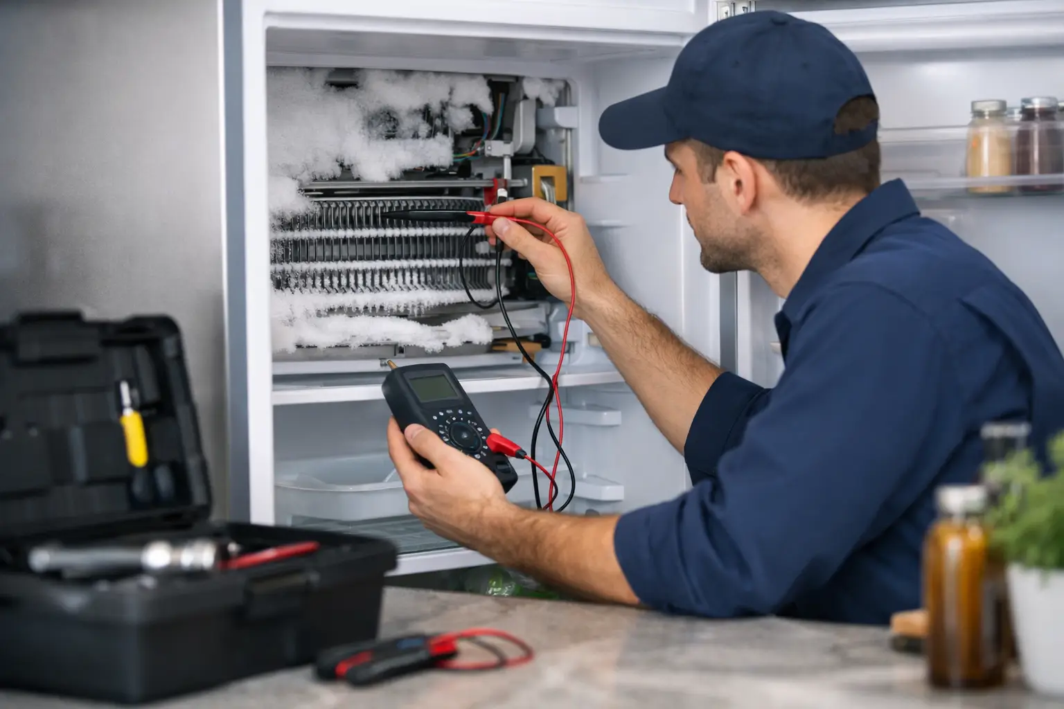
A freezer packed with white frost can make a refrigerator look like a sealed-system failure to an inexperienced technician. Usually, it is not. When the evaporator is buried under ice while the compressor and fans are still running, refrigerator defrost system diagnosis becomes a circuit-testing job: identify which component failed, prove it with measurements, and avoid selling a customer a part based on guesswork.
That workflow is valuable on day one in the field. Defrost failures are common, visible, and often repairable without opening the sealed system. They also teach the habits that separate a parts changer from a technician: reading the frost pattern, following the wiring path, checking component state, and documenting evidence before recommending a repair.
Start With the Frost Pattern, Not the Parts
A no-cool complaint does not automatically mean a defrost problem. Start by confirming what is actually happening inside the freezer. A true defrost failure usually creates heavy, fairly even frost across most or all of the evaporator coil. Air cannot move through the ice, so the freezer temperature climbs and the fresh-food section becomes warm first.
A sealed-system restriction or low refrigerant charge produces a different pattern. You may see a small frost patch near the capillary tube entrance while most of the evaporator remains bare. That is a sealed-system clue, not a heater, thermostat, or control-board diagnosis.
Also inspect the basics before disassembling the evaporator cover. Confirm that the evaporator fan operates when the door switch is closed, condenser airflow is not blocked, gaskets seal, and the drain trough is not overflowing into a sheet of ice. A frozen drain can accompany a defrost issue, but it is not proof that the defrost circuit failed.
Take photos before melting anything. A clear frost-pattern photo, model number, temperature reading, and notes about fan operation create a stronger job ticket and give the customer a defensible explanation of the repair.
The Defrost Circuit You Are Actually Testing
Most conventional refrigerators use a defrost heater, a temperature-limiting device, and a control that initiates and ends defrost. The hardware changes by manufacturer and model, but the diagnostic logic stays consistent.
The heater is mounted beneath or around the evaporator. Its job is simple: generate enough heat to clear accumulated frost. The limiting device may be a bimetal thermostat, a thermal fuse, or a thermistor-based control strategy. It prevents overheating and tells the control when the evaporator has reached the required temperature.
Older platforms may use a mechanical defrost timer. Many newer units use an adaptive defrost control board or main electronic control. Instead of initiating defrost on a fixed schedule, these controls estimate need from door openings, compressor run time, temperature inputs, and other operating data.
That distinction matters. A heater can have correct resistance and a bimetal can close when cold, yet the unit will still ice over if the board never sends power during defrost. Conversely, replacing a control board without checking the heater circuit is an expensive guess.
Refrigerator Defrost System Diagnosis: A Repeatable Workflow
A disciplined workflow protects you from bad assumptions. Disconnect power before accessing wiring or performing resistance tests. Use lockout/tagout practices when working where another person could restore power. Melt enough ice to expose components without damaging the evaporator tubing, wire insulation, or plastic liner.
1. Identify the Defrost Design
Read the model tag and verify the wiring diagram or technical sheet for that exact platform. Determine whether the refrigerator uses a timer, adaptive control, defrost heater assembly, bimetal thermostat, thermal fuse, or evaporator thermistor.
Do not assume wire colors or connector locations are universal. A refrigerator with an inverter compressor and an electronic control may use a very different defrost strategy than a basic top-freezer unit, even when the symptom looks identical.
2. Test the Heater for Continuity
With power disconnected, isolate the heater circuit as directed by the wiring diagram and measure resistance across the heater terminals. An open reading generally indicates a failed heater. A measurable resistance value indicates continuity, but it does not prove the entire defrost system is good.
There is no single resistance number that applies to every refrigerator. Heater wattage and configuration vary. Compare your measurement to model-specific service information when available, and inspect terminals for heat damage, corrosion, or a loose connector that can open the circuit under load.
3. Check the Defrost Thermostat or Thermal Limiter
A bimetal thermostat must be cold enough to close. If you test it warm at room temperature, an open reading may be normal. Place the sensor in an ice-water environment or allow it to remain on a cold evaporator, then test continuity according to its operating specifications.
A thermal fuse typically remains closed until it fails. If it is open, replace it only after determining why it opened. Installing a new fuse without inspecting heater placement, control behavior, and airflow can turn a callback into a repeat failure.
For thermistor-driven systems, measure resistance at the proper temperature and compare the reading to the manufacturer temperature-resistance chart. Thermistor diagnostics are not about deciding whether a number "looks close." They are about matching temperature, resistance, connector condition, and control-board interpretation.
4. Verify the Control Can Initiate Defrost
If the heater and safety devices test correctly, move upstream to the timer or electronic control. A mechanical timer may allow manual advancement into defrost. On electronic units, the service procedure may provide a forced-defrost mode through a control-panel sequence, test pins, or diagnostic menu.
Use the manufacturer procedure. Then verify whether the control sends the specified voltage to the defrost circuit while the system is in defrost mode. This is live-voltage work and should only be performed by a trained technician using proper meter category ratings, insulated probes, and safe meter handling.
Voltage present at the heater circuit with no heat points back toward the heater, limiter, wiring, or connection. No voltage from a properly commanded defrost cycle can point to a failed board, but only after required sensor inputs and harness continuity have been verified.
5. Inspect Wiring and Drainage Before Reassembly
A continuity test at the component does not eliminate a broken harness conductor, backed-out terminal, or corroded connector. Flex points near hinges, connectors exposed to moisture, and wire runs near sharp metal edges deserve attention.
Finish the repair by clearing the drain path. Flush it carefully, confirm water reaches the drain pan, and make sure the evaporator cover and air ducts are reinstalled correctly. A cover installed improperly can reduce airflow enough to create another cooling complaint that looks unrelated to the original repair.
Avoid the Most Expensive Diagnosis Mistakes
The most common mistake is diagnosing through a frozen evaporator without fully exposing the components. Ice hides burned terminals, displaced bimetals, and broken heater glass. The second is testing a bimetal warm and calling it defective. The third is replacing a control board because it is the most visible electronic part in the circuit.
Another costly error is treating every warm refrigerator as a defrost failure. A failed evaporator fan, poor door seal, condenser problem, or sealed-system fault can produce similar customer language: "The fridge is warm and there is ice in the freezer." Your job is to translate that complaint into observations and measurements.
Customer communication matters here. Instead of saying, "The defrost is bad," explain the failed component and the evidence: the evaporator was fully frosted, the heater circuit measured open, or the control entered forced defrost but did not deliver output voltage. That documentation supports the estimate, protects your reputation, and makes future service easier.
Build a Field-Ready Defrost Diagnostic Habit
Defrost troubleshooting is a compact version of professional appliance repair. You observe the machine, consult documentation, test safely, isolate the failed point, and verify the repair. The same process applies when you move into thermistor diagnostics, compressor controls, dishwasher heat circuits, and laundry appliance fault tracing.
Appliance Repair Academy trains that process through structured 12-week coursework, scenario-based simulations, electrical testing practice, and diagnostic workflows built for actual service calls. The goal is not to memorize a list of likely parts. It is to build the confidence to walk into a customer’s kitchen, control the diagnosis, and produce a repair recommendation you can stand behind.
If refrigerator defrost system diagnosis is the kind of hands-on problem you want to solve for a living, explore the Academy page for this article and the Appliance Repair AI app download page. Strong technicians do not guess faster - they test with purpose, document the result, and turn technical skill into paid work.